Single-point grounding is the most critical element of a three-part process involving effective bonding and grounding, transient voltage surge suppression and structural lightning protection. “Single-point grounding” is a current buzzword in protecting communications sites from the ravages of lightning and general ground transients.
Bruce A. Kaiser, President of Lightning Master, Clearwater, Florida.
What is single-point grounding? Actually, the term, as used here, is a misnomer. Single-point ground electrical potential referencing has nothing to do with the grounding system itself or with the provision of only a single path from a particular piece of equipment back to the internal grounding provisions. The grounding system is determined by the soil conditions and other factors at a specific site. As a practical matter, it is impossible to provide modern equipment with one, and only one, ground return path to the internal grounding provisions. Single-point ground electrical potential referencing means connecting all site equipment to the grounding system at a single point, or, more precisely, bonding all communications site equipment to the grounding system in such a way that all of the equipment samples ground potential at one, and only one, point (hence, single-point).
‘Potential ‘Damage
A change in electrical potential in and of itself does not damage equipment. It is a difference in electrical potential across or within a piece of equipment that causes damage. If one radio is connected to both the coaxial cables from the tower and to a power supply, and there is a difference in electrical potential between those two services, that difference in potential equalizes within the radio, causing damage or accelerated wear. The same risk applies to two pieces of equipment communication with one another through data lines. If there is a difference in electrical potential between the two pieces of equipment, that potential equalizes through the data lines within one or both pieces of equipment. (Communications site equipment, in this case, refers only to electrical or electronic equipment. Communications site equipment does not include door frames, air conditioning ducting or the tower.)
Single-Point Ground Definition
Envision an imaginary plane at or just below the floor of the site. All of the site equipment is appropriately bonded together above this plane, and an appropriate grounding system is established below this plane. Those two systems are bonded together at one, and only one, hole through that plane. Therefore, all equipment within the site is at the ground potential of that single point. The single-point ground is defined as the point at which the unified ground passes through this plane.
Several ground potentials are involved in a typical communications site. The first set of ground potentials is associated with ac power, telephone lines and RF transmission lines to the site. The second set is associated with the various electrical and electronic equipment chassis. There are other sources, too, but the following information covers these two.
Changes in ground potential across a site may be caused by a variety of factors, but the most dramatic and familiar is lightning. During a thunderstorm, the charge at the base of the storm cloud induces a shadow of opposite charge on the surface of the earth beneath it. As the storm cloud blows along through the atmosphere, this ground charge, or more accurately, earth surface charge, is dragged along the surface of the earth beneath it.
Cloud-to-ground lightning results when the difference in electrical potential between the storm cloud charge and the ground charge exceeds the dielectric of the intervening air. That air breaks down in a series of steps, and the lightning strike occurs. When lightning strikes a particular point on earth, the ground charge at that point is vacated relative to the surrounding ground charge. The surrounding charge rushes to the point of the strike.
Ground charge distribution
Looking at the distribution of ground charge immediately after a strike, it is apparent that the ground charge potential will change with distance from the strike. A point close to the strike will be at a quite different potential compared to another point at a greater distance from the strike. If a ground rod is driven at each of these points and the electrical potential between the two rods could be measured during a lightning strike, the measurement would indicate a dramatic and almost instantaneous difference in potential between the ground rods. If a power supply were grounded to the other, during a strike the radio would see a difference in electrical potential between its power input and chassis. This difference in electrical potential will equalized within the radio.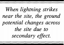
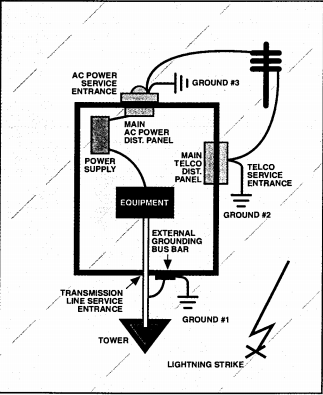
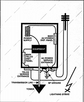
At many sites, the ac power service entrance is at one end of the equipment shelter, the telco service entrance is at one side, and the transmission line service entrance is at the end opposite the ac power entrance. (See Figure 1) Each service is grounded where it enters the shelter. When lightning strikes near the site, the ground potential changes across the site due to secondary effect. The propagation rate of the ground charge causes a difference in ground potential (dashed lines) at each service entrance ground. The equipment within the shelter therefore sees a difference in potential between the RF input at the potential of ground No. 1, the power input at the potential of ground No. 3, and the telco input at the potential of ground No. 2. That difference in potential is equalized across and within the equipment, causing wear or damage.
Transmission Line Ground
With respect to the ground potential of the services to the site, the most difficult service potential to control is the transmission line from the tower. This potential is difficult to control in part because the tower usually is several yards away from the shelter, and the tower’s potential is constantly changing.
The transmission line ground potential can be limited relative to the rest of the site, or the transmission line potential can limited relative to the rest of the site, or the transmission line potential can be made the reference potential for the remainder of the site equipment. Based on experience with Florida cell sites, the second solution is easier to implement- and actually more effective.
Grounding Configuration
The transmission line potential can be made the site reference potential (single point) by placing a large copper bus bar on the equipment shelter’s outside wall just below the transmission line service entrance. A grounding kit is installed on the transmission line services entrance. A grounding kit is installed on the transmission line (in addition to the grounding kits already installed at the top and bottom of the tower) and bonded to the bus bar. A large lead is run from the bus bar to the site grounding system. This configuration places the RF side of the site equipment at the potential of this bus bar. (See Figure 2)
 Then we route the ac service to the site so it meets the equipment shelter just to one side of the transmission line service entrance. At the main disconnect, the ac neutral and ground are bonded together, and a ground lead extends form that box. This ground lead should be attached to either the transmission line service entrance bus bar or to the large ground lead from that bus bar above the point at which it attaches to the grounding system. This assures that the ac power side ( and low voltage power side) ground of the site equipment will be at the same potential as the transmission line bus bar and therefore at the same potential as the RF side to the equipment. (See Figure 3, right.) Then the telco service is routed to the site so it meets the equipment shelter on the opposite side of the transmission line service entrance. The ground lead extending from the telco service box is attached either to the transmission service entrance bus bar or to the large ground lead form that bus bar above the point where it attaches to the grounding system. This configuration assures that the telco side of the site equipment is at the same potential as the transmission line bus bar and therefore at the same potential as the RF and power sides of the equipment.
 With this arrangement, any difference in ground potential among services to the site is equalized at the single point, and the site equipment samples all ground potentials at the one, and only one, point: and the site equipment samples all ground potentials at one, and only one, point: the single-point ground. A nearby lightning strike would produce the same step potential across the site, but because all site equipment is attached to services sampling the ground potential at only one point ( and there is no other ground reference potential), the equipment sees no current flow across or within it to equalize electrical potential.
Converting Existing Sites
This arrangement is effective and easy to design into a new site. But what about an existing site? The internal distribution routing of ac power and telco lines is already established, and it is difficult and expensive to change it. The answer is to leave the existing internal distribution routing intact and just move the service entrances. With the ac power, move the main disconnect to a location near the transmission line service entrance and ground it to the single point. Then run a “primary jumper” internally back to the existing distribution panel. This way, none of the distribution routing needs to be changed.
The same technique should be employed with the telco service. Move the demarcation or service entrance to the transmission line service entrance and establish its ground at the single point.
As expensive as it may be to move service entrances, it is less expensive than replacing damaged equipment or equipment that wears out prematurely. At least it is not necessary to reroute the internal distribution of the ac power and telco lines within the shelter.
Chassis Grounding
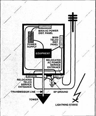
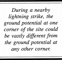 The next area of grounding concern is chassis grounding. In many sites, particularly older ones, an internal halo ground was installed around the perimeter of the shelter near the ceiling or floor and bonded to ground at all four corners of the shelter. (See Figure 4, above left) Site equipment then was bonded to the halo at the closest or most convenient location, so that piece of equipment sampled ground potential at the closest grounding point. During a nearby lightning strike, the ground potential at one corner of the site could be vastly different from the ground potential at any other corner. The chassis potential of each piece of equipment will be closest to the potential of the ground at the nearest corner of the building. The chassis potential of component A, as shown in the figure, will be close to the potential of ground No. 4. The chassis potential of component C will be close to the potential of ground No. 5, and the chassis potential of component E will be close to the potential of ground No. 2. Because many pieces of equipment communicate with one another through data lines, and all of them share the power source, electrical potential differences equalize within and through the site equipment.
Interior Bus Bar
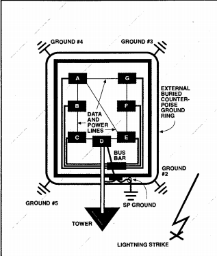
The solution is to bond the chassis of each piece of equipment to ground at the same point. ( See Figure 5) The easiest method is to install a copper bus bar inside the shelter on the opposite side of the same wall as the external transmission line bus bar. Each piece of site equipment is bonded to the internal bus bar, preferably with a bonding wire run from each chassis directly to the bus bar. The internal bus bar is bonded through the wall to the external bus bar. Ideally, equipment ground leads should be arranged across two internal bus bars according to how they produce or absorb surges, and whether they require non-isolated or isolated signal ground reference. Whatever the case, all equipment should be chassis-grounded to one potential.
A nearby lightning strike now would produce the same step potential across the site, but because all site equipment chassis sample ground potential at only one point, and there is no other ground reference potential, the equipment sees no current flow across or within it to equalize electrical potential.
Buried Counterpoise
 The real purpose of the external buried counter counterpoise around the shelter is to protect people and the site from the adverse effects of step potential across the site during a nearby lightning strike; therefore, the counterpoise is important and should be part of any site grounding scheme. Even so, its purpose is not to provide a convenient “bus” to which equipment grounds should be tired.
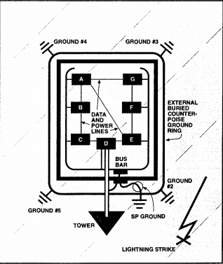
The single-point chassis ground is effective and easy to design into a new site, But what about existing sites with internal halos grounded at multiple points to the external buried counterpoise? Fortunately, many problems at an older site can be solved with a good pair of wire cutters. First, ground the internal bus to the external bus ground lead. Then cut the internal halo at the end of the building away from the transmission line service entrance, eliminating the large ground loop. Then cut all wires grounding the internal halo to the external buried counterpoise and remove them from the walls. This modification leaves each equipment chassis grounded only at the single-point bus bar. During this process, be certain not to leave any piece of equipment ungrounded inadvertently. (See Figure 6.) One of the ironies in this case is that it is less expensive ad uses less material to ground the site properly than to install a multiple-point ground.
Direct Lightning Strike
In all of the previous examples, a nearby lightning strike has been the cause of damage. A direct strike to the tower, equipment shelter or utility service pole on the site produces an even more impressive change in ground potential across the site. With a properly designed and installed single-point grounding system, the site should survive the ground potential change of even a direct strike. The electromagnetic pulse (EMP) and other effects of a close strike, and methods of mitigating their damage, are another story, but they are not covered in this article.
 A few matters become apparent when considering single-point grounding of all services and equipment. The most obvious is that it is much easier to design a new site to this standard than it is to modify an existing site. Equipment shelters can be specified and ordered from the manufacturer with all service entrances at the same end of the shelter and adjacent to the one another. Site layout can specify that the shelter. By the way, if the site has water from a commercial service or from a well, the water pipe should enter the facility at the same location and should be bonded to the single point. If the shelter has a structural lightning protection system one of its grounding points should be bonded to the single point.
Transient Suppression
If single-point grounding manages to reduce all equipment chassis and service grounds to the same electrical potential, what about the “hot” or “line” sides of those services? Any excess difference in electrical potential between the line side and the unified ground still will cause equipment damage or accelerated wear. Single-point grounding does not and cannot resolve that issue: therefore, it is important to install transient voltage surge suppression (TVSS) equipment in a “ Staged protection” design, with the primary TVSS device at the service entrance, to prevent equipment damage caused by an excess difference in electrical potential between the ground and hot or line sides of the services.
Lightning protection is a three – part process involving effective bonding and grounding, transient voltage surge suppression and structural lightning protection. Without all three elements, site equipment is not protected. Single-point grounding is but one element; nevertheless, it is probably the most basic element and the most critical to design into a site. The single-point grounding concept is not empty theory. It has been field-tested in the most lightning-damage-prone areas of the country and has proven to be effective. Put this simple concept to work to reduce damage and equipment wear.