[vc_section][vc_row][vc_column][vc_single_image image=”5130″ img_size=”full”][vc_column_text]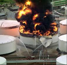 Providing adequate and effective lightning protection for storage tanks constitutes a beneficial and cost-effective step in assuring both personnel safety and reliability. Fortunately, securing such protection is not difficult or complicated, and guidance is readily available. It helps to become familiar with some basic recommended practices and standards for reference. We will be referring to the National Fire Protection Association NFPA 780, Standard for the Installation of Lightning Protection Systems; the American Petroleum Institute API 545, Recommended Practice for Lightning Protection of Aboveground Storage Tanks for Flammable or Combustible Liquids; and the American Petroleum Institute API 2003, Recommended Practice for Protection Against Ignitions Arising Out of Static, Lightning, and Stray Currents.
Whenever considering lightning protection, it helps to fall back upon the three basic steps: bonding and grounding, surge suppression, and structural lightning protection.
BONDING AND GROUNDING. The first consideration is bonding and grounding. According to API 545, flat-bottom tanks are inherently self-grounding for lightning protection purposes. The mass of the tank and surface area of its bottom in contact with whatever material it occupies provides a sufficiently low-impedance path to conduct lightning currents without increasing the risk of ignition. This applies whether or not a non-conductive containment membrane is in place under the tank.
It should be noted that, although adequate for lightning grounding, the path to ground may be high resistance, rendering it unsuitable for AC power grounding. In the event of an AC power ground fault, the lack of a low-resistance return path may leave the tank energized. Therefore, we recommend at least one, and preferable one each 100’ of tank perimeter, “solid” connection to ground. This usually consists of a conductor attached to a grounding tab at the base of the tank shell running to a ground rod or to the grounding grid.
Bonding is simply a matter of electrically connecting different masses of inductance (metallic masses) together to maintain them at the same potential, to equalize changing potential, and to provide a path for lightning current between them.
The major area of concern is obviously the floating roof. On an external floating roof tank, there are three lightning events that can cause arcing between the roof and tank shell. The first is a direct strike to the roof itself or its appurtenances. In this case, all of the lightning energy must flow across the seals to the tank shell and to ground. The second is a direct strike to the top of the tank shell. In this case, the lightning energy flows down the shell to ground, and a large difference in potential is produced between the roof and shell. That potential must be equalized to prevent ignition. In the third case, a nearby strike changes the potential of the tank shell, and much less difference in potential must be equalized between the roof and tank shell.
Lighting energy consists of two components with an intervening transition component. The first is a high-energy, short-duration pulse of energy. The second is a lower-energy, longer-duration wave event. The first segment, although conveying high amperage, is so short (millionth of a second) that it does not normally cause ignition. However, it does initiate sparks/arcs between the shell and roof. Think of passing your finger quickly through the flame of a candle; very short exposure to the flame, i.e. spark, does not result in a burn. The second segment consists of a few hundred amps (about equivalent to the electrical service into your home) and lasts thousands of times longer than the first segment. Due to the resistance of sliding contacts between the shell and roof, the arc is sustained throughout the long duration and maintains the heat at the arc locations. This magnitude and duration can easily produce sufficient heat to cause the ignition of any flammable gasses present. This is analogous to holding you finger in the flame.
To address the two components, two types of contacts are required between the floating roof and tank shell. The first is a sliding contact, and is intended to handle the short-duration, high-energy pulse. This has historically been addressed by the use of shunts between the roof and tank shell. These were developed to overcome the shortcomings of non-conductive seals. However, most modern tanks employ metallic shoes as the primary seal between the roof and shell. These shoes have many times the surface area of shunts. According to wording which will presumable be adopted in the next revision of both NFPA 780 and API 545, the presence of primary metallic shoe seals will negate the requirement for shunts.
Shunt Primary Metallic Shoe Seals
However, contacts sliding on contaminants produce arcing and sparking, raising the need for a second type of conductor, the bypass conductor. This is a hard electrical connection between the floating roof and tank shell. Due to the characteristics of the lightning energy and because the bypass conductor must be of sufficient length to allow full range of motion of the tank roof, it does not have much of an effect on the first component of the strike. It is the second component, where the true danger lurks, that it becomes most effective. Due to its permanent low resistance bond, it conducts the second segment of the lightning strike better than the sliding contacts and quenches any arcing that may be present. Thus preventing ignition.
Bypass conductors
Another area of concern is thief hatches. The hatch itself rests on a rubber seal and is connected to its collar by a pin-type hinge. In the field, we have measured a high resistance between the thief hatch and its collar. Lightning current flow across that resistance is capable of producing sufficient heat and arcing to cause ignition. Therefore, a flexible jumper between the hatch and collar should be added to each.
SURGE SUPPRESSION. The second step in securing adequate protection is surge suppression. Any conductor running to or from a tank is vulnerable to the secondary effects of lightning. Surge damage to equipment and electronics connected to those conductors is responsible for millions of dollars of lost revenue in multiple categories. A surge suppressor is a device that keeps that from happening. Typical conductors found on a tank include AC power for site lights, pumps, valves, etc. Further, there is an abundance of low-voltage instrumentation and control (I&C) circuits used for data collection and proper operation of the facility. Surge suppressors should be installed at the tank end of such conductors to protect the field instrumentation and also at their marshaling cabinet end to protect the control system.
STRUCTURAL LIGHTNING PROTECTION. The third step in securing protection is structural lightning protection. When we think of structural lightning protection we normally think of lightning rods on the roof of a building. It is important to remember that the purpose of a lightning rod system is to convey lightning energy around a non-conductive structure, such as a house or barn, thereby keeping that structure from burning down.
Note that there is absolutely no benefit to installing conventional lightning rods on a tank. According to NFPA 780, the tank itself is inherently self-protecting. There are three components that make up a lightning rod system: the lightning rods, conductor system and grounding system. On a tank, the tank itself is of sufficient thickness to be substituted for the lightning rods, the shell is of adequate cross section to be substituted as the conductor system, and the site ground is more than adequate for lightning protection purposes. Therefore, the tank is self-protecting without the need to install additional components. Lightning rods would only tend to attract lightning to the tank.
There is, however, a technology alternative to conventional lightning rods. These are streamer-delaying air terminals. These air terminals, colloquially known as “fuzzy ball™” lightning rods, are designed to interrupt the lightning completion process by delaying the formation of lightning-completing streamers from objects on the surface of the earth.
A lightning strike begins with the formation of stepped leaders from the base of the storm cloud. These leaders jump in steps of around 150’, propagating downward towards the surface of the earth. When they reach to within 500’ or so of the surface, they begin pulling streamers of ground charge off of objects on the surface. Whichever streamer meets a stepped leader first completes the circuit, thus determining what gets hit. Conventional lightning rods are streamer generators.
As the ground charge builds on a streamer-delaying air terminal, instead of a sudden breakdown into streamer formation as with a conventional lightning rod, the multitude of sharp points produce corona under a relatively low potential, bleeding off the charge in a more controlled and consistent manner. With the Fuzzy Ball, the ground charge that would have established the streamer has already been partly dissipated into the atmosphere, thereby delaying or preventing streamer formation, thus reducing the likelihood of a direct strike.
Lightning Master uses NFPA 780 as the design standard for protecting a tank. Since the tank contains flammable material, we reduce the diameter of the rolling sphere to 100’, reducing the spacing between air terminals to jus over 12’. We install them around the perimeter of the tank shell on the foam injection plates and rim, and on the gauging platform. We also install them on the walkway handrail, if one is installed.
Streamer delaying air terminals on storage tanks
API 2003, Annex C, Direct Stroke Lightning Protection, C.1 notes that conventional lightning protection systems do not protect against indirect lightning currents or induced voltages. These are both major causes of ignition, particularly in production tanks. It further notes in C.2.1 that, according to vendor claims, streamer-delaying systems may have some benefit in protecting against indirect lightning currents of induced voltages. This type of performance is obviously preferable.
In the real world, we have seen a very high success rate with operators installing this type of system. Indeed, the cost has been justified many times over in both savings associated with extinguishing a fire and in reducing lost time in service.[/vc_column_text][/vc_column][/vc_row][/vc_section]