
Overview
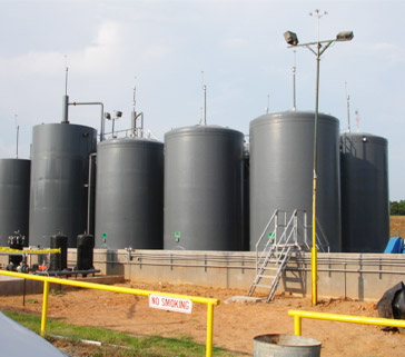
Over the years, there have been an inordinately high number of ignitions caused by lightning and static at petroleum production and disposal sites. Because of the nature of the sites, there is no single lightning/static protection standard that specifically applies to them. Therefore, Lightning Master Corporation, working with operators and employing existing standards, has developed such a program.
Since these are petroleum industry sites, we began with the American Petroleum Institute API 2003 (Protection Against Ignitions Arising Out of Static, Lightning, and Stray Currents) and API 545 (Recommended Practice for Lightning Protection of Aboveground Storage Tanks for Flammable or Combustible Liquids). We adopted the principles contained in these standards for overall lightning protection and particularly for grounding. Since the API documents did not adequately address structural lightning protection design or layout, we applied NFPA 780 (Standard for the Installation of Lightning Protection Systems) for that part of the system. We also applied Underwriters Laboratories UL 96 (Standard for Safety – ANSI/CAN/UL 96:2016, Lightning Protection Components) and UL 96A (Standard for Safety – Installation Requirements for Lightning Protection Systems). These turn the principles found in NFPA 780 into material and installation guidelines. For static control, we referenced the American Petroleum Institute API 2003 and National Fire Protection Association NFPA 77 (Recommended Practice on Static Electricity).
There are two related causes of ignition in production, disposal and flowback tanks: static from normal operations and lightning. Static charge accumulation inside a tank occurs in the vapor droplets suspended above the stored product. Static charge accumulation on the exterior of a tank may be caused by atmospheric conditions, such as sand, dust or dry snow blowing across and around a tank. If the charge reaches a sufficient voltage, it may arc to an object at a different potential. If the arc has sufficient energy to reach an incendive level and occurs in a flammable mixture, it may cause a fire or explosion (API, 4.1). Lightning stroke ignition is caused by the heating effect of lightning attachment in the presence of flammable gasses or by secondary effect or electromagnetic effect (EMP) arcing. In any case, ignition is dependent on the presence of a flammable mixture at the arc, either inside or outside the tank.
Although their use is discouraged by American Petroleum Institute (API) standards, many operators use fiberglass tanks for corrosion control. Fiberglass tanks exhibit a much higher likelihood of being involved in an ignition than steel tanks. There are no standards for protection of fiberglass tanks, so Lightning Master developed a system to bond all metallic masses on these tanks together and to the remainder of the site.
The systems solution to reducing the likelihood of ignition consists of three components: bonding and grounding, in-tank static control, and structural lightning protection.
Bonding and Grounding
- Bonding consists of electrically interconnecting all masses of inductance (metallic objects) at the site with conductors or through existing conductive piping, handrails and other structures so they are at the same potential. If they are maintained at the same potential, there is no opportunity for arcing between them. Bonding also consists of installing bonding jumper conductors across gaps created by insulators, such as between a thief hatch and its collar.
- Grounding consists of connecting the bonded mass of the site structures and components to earth using the inherent self-grounding of flat-bottom metal tanks, the site grounding grid (if installed), and/or ground electrodes (rods), if desired.
In-Tank Static Static Control
- Inside the tank static control consists of installing in-tank static drains (inductive neutralizer as described in NFPA 77, 8.1.2) in each tank likely to contain produced water or other flammable gas producing product to bleed off static charge and to equalize the potential of the vapor and liquid to the bonded mass of the site. Outside-the-tank static control consists of installing dissipating-type air terminals (akin to static wicks on airplanes) on the structure.
Structural Lightning Protection
- This consists of adding an NFPA 780 type (UL 96 and 96A) structural lightning protection (lightning rod) system to the site to prevent lightning attachment or current flow from damaging site components. Since the likelihood of ignition of a site is highly likely in the event of a direct lightning attachment in the presence of flammable gas, we recommend the use of streamer-delaying air terminals to possibly reduce the likelihood of a direct lightning attachment. There is some controversy concerning the efficacy of this technology, much of which is generated by conventional lightning rod manufacturers (think buggy whip makers). However, if an air terminal offers even the possibility of reducing the likelihood of a direct lightning attachment, its use is preferred.
System description:
1.0 Bonding
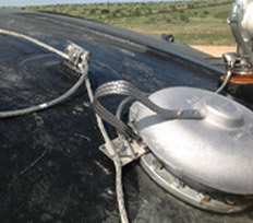
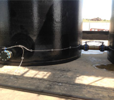
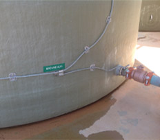
1.1 Each metal object on non-conductive piping or on a non-conductive (fiberglass) tank or tank battery shall be electrically bonded to all other metal objects by means of a lightning protection conductor sized not smaller than NFPA 780 Class I (1/0 stranded or braided conductor or equivalent). This shall include vent pipes, vent pipe manifolds, in-tank static drains, thief hatch collars, handrails, carbon veil ground lugs, drain pipe valves, bull plugs, etc. Conductive components located on the site, such as steel piping, walkway handrails, etc. may be used as main and bonding conductors.
1.2 Exposed conductors shall be routed along the top of piping for direct lightning strike protection and for theft mitigation.
1.4 Metal objects located on a steel tank shall be considered to be bonded inherently through the tank structure.
1.5 The electrically bonded mass of the site shall be bonded to any truck loadout bonding conductor (if installed).
1.6 Each tank appurtenance with an insulating gasket, such as a thief hatch, shall be equipped with a flexible bonding conductor across the insulating gasket.
1.7 All bonding clamps shall be designed for the purpose, and shall preferably be of stainless steel.
1.8 Conductive piping, handrails, structural components, etc. a minimum of 0.064” thick may be substituted for cable or wire conductors.
1.9 Any electrically isolated sections of piping or structure shall be bonded to the bonded mass of the site.
1.10 Joint taping or doping shall not render a metal pipe joint non-conductive for this purpose.
1.11 Small metal masses, such as bolts on a fiberglass man-way, shall not require bonding, per NFPA 780, 8.5.3.1 and 8.5.3.2.
2.0 GROUNDING
2.1 For lightning protection and static control purposes, flat-bottom metal tanks shall be considered inherently self-grounding (API 545, A.2.1 and NFPA 77, 7.4.1.1). This applies whether or not a containment liner or barrier is installed either in or under the tank (API, A.2.2). If a steel tank is installed on top of an insulating base, such as Styrofoam blocks, it shall not be considered to be self-grounding. These tanks shall be grounded in accordance with the requirements of NFPA 780, 7.3.7.2 (1) or (3).
2.2 If a ground grid is installed at a site, each structure at that site shall be bonded thereto either individually or through the site bonding system.
2.3 On fiberglass tanks all metal objects shall be bonded together, and have a minimum of one connection to ground. A steel tank complying with Section 2.1 may be used as ground for other tanks, components, or bonded masses (API 545, 3.6).
2.4 Conductive piping, walkway handrails, tanks, etc. a minimum of 0.064” thick shall be permitted to be used as main, down, and bonding conductors.
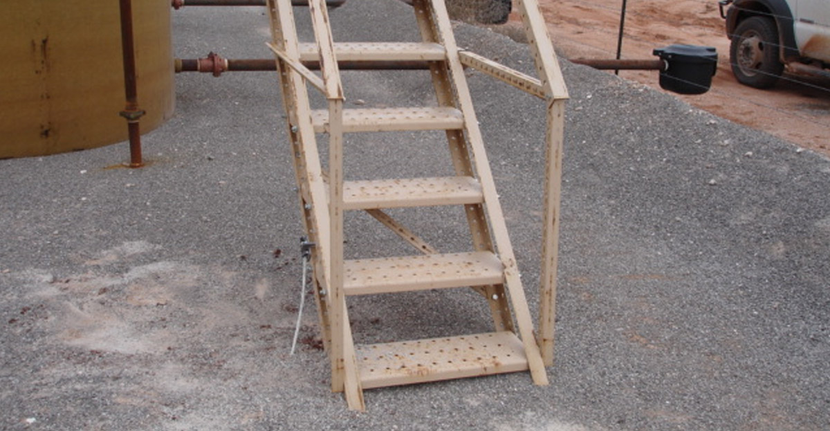
2.5 Additional grounding electrodes (NFPA 780, 4.13) are permitted to be installed for supplemental grounding. A reasonable location for supplemental grounding is at the bottom of stairways and ladders, as this may also provide a measure of personnel protection. Supplemental grounding by means of driven ground rods neither decreases nor increases the probability of a direct lightning strike, nor does it reduce the possibility of ignition of the contents in the event of a direct lightning strike (API 2003, 5.4.1).
2.6 Conductors may be routed over the top of containment berms to interconnect supplemental grounding electrodes located outside the berm.
2.7 Metallic piping buried for a minimum length of 10’ may be substituted for a ground rod.
2.8 Grounding for purposes other than lightning and static protection is not addressed herein, but should be considered by the operator.
3.0 IN-TANK BONDING AND STATIC CONTROL – Lightning Master In-Tank Static Drain (ITSD)
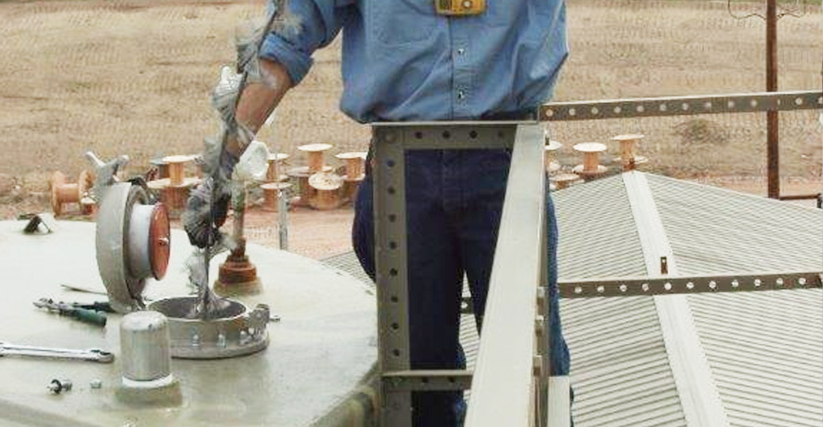
3.1 Each tank containing a flammable liquid or liquid capable of producing flammable vapors or gas shall be equipped with an internal static drain (inductive neutralizer) as described in NFPA 77, 8.1.2.
3.2 Each in-tank static drain shall be constructed to present multiple, small radius (not to exceed .010” diameter) dissipation electrodes to the vapor space and the stored product.
3.3 Dissipation electrodes shall be flexible, so as to be durable and to present a minimum of loosening force on their attachment points and to shed paraffin and other contaminants.
3.4 Each in-tank static drain shall be provided with provisions to secure it mechanically and electrically to the thief hatch collar or other suitable, grounded appurtenance at the top of the tank.
3.5 Each in-tank static drain shall extend from the roof of the tank through the vapor space above the stored product, penetrate the surface of the stored product, and extend a minimum of one foot below the lowest level of the stored liquid or to within six inches of the bottom of the tank, whichever is lowest. The static drain shall be of sufficient length and rigidity that it penetrates the surface of the contained product at all operating fill levels.
3.6 Each static drain shall be constructed in one continuous length for maximum strength and durability. Splicing of shorter lengths shall not be permitted.
3.7 Each static drain shall be constructed of stainless steel or other suitable alloys or materials to withstand corrosion and mechanical forces.
3.8 The electrical resistance of the static drain shall not exceed .5 Ω per 50’ length.
4.0 STRUCTURAL LIGHTNING PROTECTION
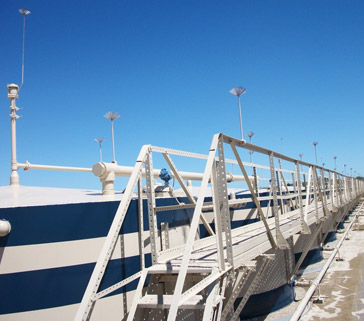
4.1 Air terminals (lightning rods) shall be installed on each tank, handrail, vent pipe, etc. as required to meet the coverage requirements of National Fire Protection Association NFPA 780, 4.8.1. One or more of the following protection methods shall be used independently or in combination: Layout (placement) method (4.7); Angle method (4.8.2); Rolling sphere method (4.8.3). If the rolling sphere method is used, the radius of the sphere shall be reduced to 100’ (7.3.2).
4.2 Each air terminal shall be provided with a minimum of two continuously downward coursing paths to ground, except as noted below.
4.3 Main conductors may be coursed upward at a rate not to exceed 1/4 slope as allowed by NFPA 780, 4.9.
4.4 One way and dead-end paths shall be permitted as allowed by NFPA 780, 4.9.1 and 4.9.2.
4.5 Air terminals shall be of the streamer-delaying type, Lightning Master LM-PP series (aka “Fuzzy Ball” lightning rods).
4.6 Air terminals exceeding 24” in height shall be permitted without side bracing if that air terminal and base combination is installed on piping, steel or concrete, and is capable of withstanding a tipping force of 2.2 lbs (0.9979032 kg) per foot (0.3048 m) of unbraced elevation conductor length at its tip or alternately able to withstand a wind of 156 mph (0.3048 m/second).
5.0 General
5.1 In the event of a conflict between standards, the requirements specified in API standards shall supersede requirements specified in NFPA or UL standards.
5.2 If electrical or electronic components are installed in a NFPA 70 defined hazardous (classified) location, they shall be suitable listed for that area.
Additional considerations:
A.1 At high theft locations, metal objects at the base of a tank need not be bonded with conductors if they are continuously in contact with stored product fluid and if there is an in-tank static drain (see section 3) installed in that tank.
A.2 RISK ASSESSMENT – In determining and prioritizing the scope of work to be accomplished at a site, at a minimum, the following factors should be considered:
A.1.1 Problematic – sites that have experienced a previous static or lightning event
A.1.2 High Exposure – sites located in exposed locations such as hilltops or historically high-lightning locations
A.1.3 High Consequence – sites located in environmentally sensitive locations or populated areas
A.1.4 Accessibility – sites with limited or difficult access for remediation and repair
A.1.5 Regulatory – sites where a local/municipal/regional construction code requires lighting protection – this system is approved by the City of Ft. Worth
A.1.6 Visibility – facilities that are in a particularly sensitive area (urban or otherwise high-profile, etc.
A.1.7 Operational Considerations – high production or otherwise operationally important sites
A.1.8 Investment –those sites with significant equipment investment
A.2 FORENSIC ANALYSIS – Anytime a site suffers a static ignition or a lightning strike, experienced personnel, preferably UL certified, should be retained to assist the Owner in determining likely causes of damage and in specifying additional protection requirements.
A.3 INSPECTION AND MAINTENANCE – Because of the nature of these sites, they are often modified, expanded, reconfigured or otherwise changed. Additionally, bonding conductors and other system components are often disconnected or moved to allow maintenance of other tank systems. Therefore, each site shall be inspected after any changes are made or work is performed, and at a minimum of once per year. Please refer to the Lightning Master “Lightning Protection System (LPS) Inspection and Maintenance” document for additional information.
A.4 COMMON SENSE – Common sense should be employed in the use and sizing of components and in overall system design. If a listed or recommended bonding conductor or clamp is larger than the object to be bonded or otherwise will not “fit” because of size, shape, contour, configuration or other factor, the use of a smaller, more appropriately size or shape conductor or clamp is preferred. If a single, one-way conductor is installed to an air terminal, it may course “uphill” to follow the slope of the tank roof.
Notes:
Many sites protected by this type of lightning protection system have sustained direct and nearby lightning strikes without suffering damage. The likelihood of ignition of a site by a direct or nearby lightning stroke or arcing is primarily dependent of the presence or absence of a flammable mixture available for ignition. Therefore, steps should be taken by the operator to discourage the presence of such a mixture. Such steps may include keeping thief hatches closed, installing vapor recovery units (VRU’s), etc. (NFPA 780, 7.2.1).
NFPA 780, 7.2.1.1 states that openings where flammable concentrations of vapor or gas escape to the atmosphere shall be closed or otherwise protected against the entrance of flame. This indicates that flame arrestors may be required at certain openings. This is the responsibility of the owner/operator at initial site construction, and is not included in this lightning protection system.
This system is not designed or intended to protect personnel from lightning or static. For personnel protection, please refer to owner/operator policies and procedures. For additional information and guidance, please refer to NFPA 780, Appendix M, and API 2003, including 4.6.10.
Equipment that is part of the lightning/static protection system may have the potential to interfere, mechanically or otherwise, with other appurtenances and systems on a site. The owner/operator should evaluate the properties of lightning protection system components for any potential interference.