In 2009, API 545, “Recommended Practice for Lightning Protection of Aboveground Storage Tanks for Flammable or Combustible Liquids”, First Edition, replaced the lightning protection portion of API 2003, “Protection Against Ignitions Arising Out of Static, Lightning, and Stray Currents”. With the new Recommended Practice (RP) came the requirement for by-pass conductors between a tank floating roof and tank shell. This is in addition to and supplements the historical requirement for shunts. What are by-pass conductors and why are they needed?
API 2003 has historically recommended the use of shunts (section 5.4.2.2). Shunts are simply metallic straps, usually stainless steel, installed at intervals not to exceed 10’ around the perimeter of the roof. These shunts are mechanically attached and electrically bonded to the perimeter of the roof, and are spring-loaded to press up against the inside of the tank shell. As the roof rides up and down on the stored product, the shunts ride up and down against the tank shell providing an electrical bond between the two.
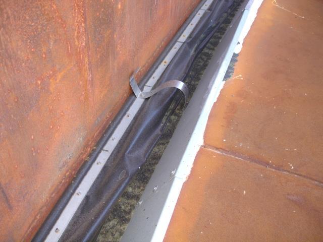
Typical shunt and secondary seal
Shunts should be installed above the secondary seal. API 2003 discouraged placing the shunts below the liquid because of inspection considerations, but that is grist for another discussion. Shunts were envisioned to permit any lightning-related current to propagate from the floating roof to the tank shell to ground without generating a spark in an area likely to contain flammable vapors. How they perform in actual service is somewhat different.
By-pass conductors are simply conductors run between the perimeter of the floating roof and the tank shell at intervals not to exceed 100’. These provide a low-resistance path between the floating roof and the tank shell.
Why are additional conductors necessary? Because although shunts provide a low impedance path, they may appear to be a high-resistance path. Current flow over resistance produces heat. Hence, they may actually produce ignition in an area likely to contain flammable vapors.
As the name implies, the roof of a floating roof tank floats on the stored product. Primary and secondary seals separate the roof from the tank wall, keeping the product in and foreign objects out. As these seals are constructed of insulating material, by its nature a floating roof is electrically insulated from the shell of its tank.
Problems arise when there is a difference in potential between the tank shell and the floating roof. Under normal conditions, the tank shell is at the potential of the earth upon which it rests. The mass of the tank and the surface contact between the tank bottom and the mass of earth causes it to assume that potential. Over time, the floating roof assumes the same potential.
There are three separate lightning events that could cause a difference in potential between the tank shell and the floating roof: a direct lightning strike to the roof, a direct lightning strike to the tank rim (including the gauging platform), and a nearby lightning strike.
In the case of a direct lightning strike to the roof, the roof changes potential immediately and dramatically. The tank rim, being at earth potential, tends to remain at that potential. As the current attempts to flow to ground through the tank shell, the current flow across the rim seals can cause arcing.
In the event of a direct lightning strike to the tank shell, usually to the rim or gauging platform, the tank shell immediately and dramatically changes potential. Due to inertia, the floating roof tends to stay at its original potential. The resulting difference in potential can cause arcing across the rim seals as the roof struggles to assume the potential of the shell.
A nearby strike produces the same effect as a direct strike to the tank shell. The ground beneath the tank changes potential as the ground charge equalizes toward the point of the lightning strike. The floating roof tends to remain at its pre-strike potential. Again, the resulting difference in potential can cause arcing across the rim seals as the roof struggles to assume the potential of the shell.
In order to have ignition, there must be a flammable mixture available where the arc takes place. This highlights the importance of well fitted, well-maintained rim seals. If the seals are performing as designed, there will be no flammable mixture, hence, no ignition. However, if the arc takes place where there are flammable vapors, the vapors may ignite, causing a rim fire. That’s why many EFR tanks are permanently equipped with foam fire suppression systems.
Shunts and by-pass conductors work in concert to equalize any difference in potential between the floating roof and the tank shell.
Why are both shunts and by-pass conductors necessary? Lightning energy is actually a multiple stage event depicted by this graph.
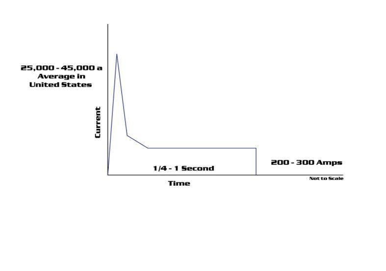
The event begins with a short-duration, high amperage discharge, followed by a lower amperage, longer duration tail. Even though the short duration transient appears more impressive, it turns out that ignition can be more directly attributable to the second portion of the event. Because of the fast rise-time of the initial front, it behaves like a high-frequency discharge, tending to follow the lowest impedance path. The tail, looking more like a direct current event, tends to follow low-resistance paths. It is important to note that actual lightning strikes are comprised of a series of strokes. The number of strokes per event is typically three to four, but, according to Martin Uman in All About Lightning, may range from one to thirty.
The shunts, being a short and direct path from the floating roof to the tank shell, offer a low-impedance path favorable for conducting the fast rise time, high energy transient. However, with the tank in service, after the tank roof makes a few trips up and down, instead of riding on bare metal, the shunts are now riding on a layer of non-conductive gunk, raising the electrical resistance between the shunt and tank shell. Current flow over a high resistance generates heat, producing sparking and potential ignition. Think of your electric kitchen stove on steroids. Although originally envisioned to prevent arcing, shunts often emit a shower of sparks as the energy travels through the resistance of the gunk. Therefore, the committee recognized the need to supplement the shunts with low resistance by-bass conductors.
By-pass conductors provide the low-resistance path necessary to conduct the lower amperage, longer duration energy from the floating roof to the tank shell without arcing or excessive heating. They may take many forms, the simplest being a wire attached to the tank rim and to the edge of the floating roof, and allowed to pile up on and straighten out from the roof as it rises and falls. The problem with this approach is that the conductor will tend to become entangled with edge seals, hatches, legs, and other appurtenances. Other approaches include reel systems or movable arm systems, such as the one shown below. The benefit of the movable arm system is its simplicity and durability.
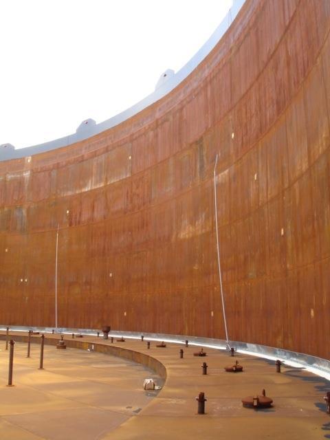
Movable Arm Grounding System (MAGS TM) (patent pending)
By-pass conductor technology is not a new approach. Richard King, of HMT Inc., recalls the days years ago when he was performing contract maintenance work for a major tank operator in Port Arthur, TX. The operator had experienced multiple incidents of rim fires from lightning strikes. To address that problem, Richard’s crews installed 8-10 lengths of 2/0 welding cable around the perimeter of each tank. The top ends of the welding cable were supported by davit arms on the tank rim extending out over the roof, with the bottom ends terminating on lugs welded to the tank roof.
This approach reduced lightning related ignitions by 98%. Unfortunately, these conductors had to be replaced often, as they became fouled on legs, hatches and other objects on the tank roof, and bent or pulled loose from the davit arms. Hence the need for an improved design for by-pass conductors, such as the MAGS design shown above. In summary, because of their lower impedance, the shunts tend to conduct the initial, high frequency-like portion of the strike. When the high resistance of the shunt to the tank shell renders them unable to conduct the lower energy tail without excessive heating and arcing, the by-pass conductors, because they are lower resistance, take over and conduct the longer-duration, lower amperage tail. The combination of shunts and by-pass conductors are also better suited to handle the subsequent return strokes that comprise a typical lightning event.
Based upon our present understanding of the phenomenon, the combination of shunts and by-pass conductors offer the optimum application of known technology to control the ignition phenomena as we presently understand it by accommodating all components of current flow from a lightning strike.